Building a DIY Motion-Triggered Module for Halloween Animatronics
| Shelf | AI & ML |
|---|---|
| Date in | |
| Readers | 669 |
This article details a DIY motion sensor module using the HC-SR501 for Halloween animatronics, highlighting its components and assembly process.
Introduction to DIY Motion Sensors for Halloween Projects
As Halloween approaches, the quest for creating spooky decorations intensifies. For makers and DIY enthusiasts, animatronics offer a thrilling way to bring creativity to life. One efficient way to trigger these animated props is through motion sensors, specifically the HC-SR501 PIR sensor. This guide focuses on building a motion-triggered module designed for Halloween animatronics, offering a compact enclosure that integrates essential electronic components to enhance the project’s functionality.
Understanding the Components
The motion-triggered module utilizes several key components that you’ll need to gather prior to assembly:
- HC-SR501 PIR Motion Sensor: This passive infrared sensor detects motion by measuring changes in infrared levels from objects in its field of view. Its sensitivity can be adjusted, making it suitable for varying project requirements.
- Sharp PC817 Optocoupler: This component isolates different sections of your circuit, protecting your microcontroller from high voltages and ensuring safe operation.
- 9V Battery Clip: The Type T battery clip provides a straightforward way to power your device, ensuring portability and ease of use.
- KCD1 Square Two-Pin On/Off Rocker Switch: Adding this switch allows you to control the power to your motion sensor and animatronics easily.
- Resistor: A 100Ω resistor is required for current limiting, particularly to protect sensitive components.
- Power Source: A standard 9V battery ensures adequate power for the entire setup, allowing for reliable operation.
3D Printed Enclosure Design
The enclosure is a critical part of the project, protecting the internal components while providing an aesthetic that fits the Halloween theme. The design recommends using either PLA or PETG filament for printing, with TPU used for an adjustable cap.
Regarding the printing parameters, it’s advised to use:
- Layer height of 0.2mm
- 25% infill for a balance of strength and weight
- Six walls for enhanced durability
Each enclosure print requires approximately 1.4 hours, allowing for quick iteration and adjustments as needed. Ensure you have no supports during printing to keep the structural integrity intact and ease post-processing.

Assembly and Wiring
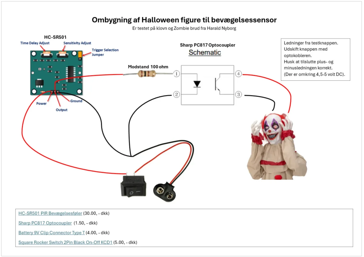
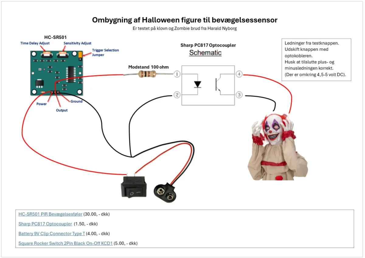
The assembly process is straightforward, especially with the provided wiring diagram. Before proceeding, it’s crucial to verify all connections to prevent short circuits that could damage your components. Here’s a step-by-step approach to assembling the module:
- Start with the PIR sensor and place it at the designated position inside the enclosure.
- Connect the output pin from the HC-SR501 to the input of the optocoupler.
- Attach the battery clip, ensuring you have the correct polarity – typically, red to positive and black to negative.
- Integrate the on/off switch into the circuit to control the power supply.
- Secure all components and close the enclosure for protection.
Once assembled, testing the functionality of the module is vital. Trigger the sensor using your hand or another object to verify that it activates the connected animatronics as intended.
Practical Applications and Future Considerations
This DIY project can serve as an entry point into automation and electronics, particularly tailored for themed events like Halloween. It’s perfect for hobbyists looking to enhance their DIY animatronic setups, making the interaction more engaging for viewers.
As enthusiasts experiment with this setup, they can explore potential enhancements that might involve integrating other sensors or even multi-channel outputs to control a more extensive animatronics system. Additionally, using a microcontroller such as an Arduino could open up possibilities for adjustable settings or programmable behaviors, enhancing the interactivity of the animatronics.
Limitations and Next Steps
While this project covers the basics of creating a motion-triggered system, it does have limitations. Factors such as the PIR sensor’s range and field of view may limit its effectiveness in larger setups. Future iterations could investigate miniaturized sensors or even integration with wireless technology for remote triggering.
Keep an eye on advancements in sensor technology, as new models with expanded functionalities regularly emerge. Adapting these updates will ensure the projects remain relevant and exciting, enhancing both the maker's experience and the end product's effectiveness.
In conclusion, building a motion-sensor module for Halloween animatronics not only hones electronics skills but also adds a lively dimension to your decorations. With careful assembly and creativity, the possibilities are virtually limitless for your DIY projects.